Hardware Hacking with Tan and Limdo
aurellem ☉
Two of my friends at 21st Century Medicine, Tan and Limdo, were interested in learning how to to do hardware and software hacking, so recently we've been getting together on the weekends and working on some simple electronics and coding projects. It's generally a relaxing time, and we always enjoy good food and lots of tea!
These first two intro projects have focused on four architectural levels:
- Hardware – soldering resistors, LEDs, etc. We lay out the basic circuit design and then actually build it in reality! This part ends with a set of wires that we can attach to the Arduino.
- Arduino microcode – We program a simple interface to the wires we just assembled and make the hardware we just built do something. Then we define an API to drive the Arduino via the serial port.
- Control Scripts – Here we use python, perl, or whatever's appropriate to make a better API to our Hardware/Arduino.
- Web Control – We build wrappers to the control scripts and use them as CGI programs to build a nice web interface to our hardware.
The purpose of doing a few projects in this style is that even though these projects are simple, they contain in minature all the things one needs to develop real products – from managing sensors and effectors to building a touch-screen interface using a raspberry pi, html, css, and a local web server.
1 Building a LED Countdown Display
I spent a wonderful Saturday shopping for teaching supplies and bought a couple prototyping boards, a bunch of resistors, LEDs, some op-amps, potentiometers, wires, some photoresistors, a soldering iorn; basically everything we'd need to have fun!
I showed Tan how to wire up an LED and how voltage dividers worked, and then he designed and built a nice numeric display like you might find on a microwave!
The LED Display cycles through each digit.
// Countdown
// April 5th, 2015
// By Robert McIntyre, Limdo Chow, and Yuansheng Tan


// LED Display maping:
//
//  1    2    3
//  4         5
//  6    7    8
//  9        10
// 11   12   13


// init LED ports for display
void setup() {
  for(int i=1; i<=13; i++){
    pinMode(i, OUTPUT);
  }
}

void set_display (int L1, int L2, int L3,
                  int L4, int L5, int L6,
                  int L7, int L8, int L9,
                  int L10, int L11, int L12,
                  int L13){
  digitalWrite(3, L1 ? HIGH : LOW);
  digitalWrite(2, L2 ? HIGH : LOW);
  digitalWrite(1, L3 ? HIGH : LOW);
  digitalWrite(4, L4 ? HIGH : LOW);
  digitalWrite(5, L5 ? HIGH : LOW);
  digitalWrite(7, L6 ? HIGH : LOW);
  digitalWrite(8, L7 ? HIGH : LOW);
  digitalWrite(6, L8 ? HIGH : LOW);
  digitalWrite(11, L9 ? HIGH : LOW);
  digitalWrite(9, L10 ? HIGH : LOW);
  digitalWrite(13, L11 ? HIGH : LOW);
  digitalWrite(12, L12 ? HIGH : LOW);
  digitalWrite(10, L13 ? HIGH : LOW);
}

void clear_all () {
  for (int i=1; i<=13; i++){
    digitalWrite(i,LOW);
  }
}

void zero() {
             // 1   2   3   4   5   6   7   8   9  10  11  12  13
  set_display(  1,  1,  1,  1,  1,  1,  0,  1,  1,  1,  1,  1,  1);
}

void one() {
             // 1   2   3   4   5   6   7   8   9  10  11  12  13
  set_display(  0,  0,  1,  0,  1,  0,  0,  1,  0,  1,  0,  0,  1);
}

void two() {
             // 1   2   3   4   5   6   7   8   9  10  11  12  13
  set_display(  1,  1,  1,  0,  1,  1,  1,  1,  1,  0,  1,  1,  1);
}

void three() {
             // 1   2   3   4   5   6   7   8   9  10  11  12  13
  set_display(  1,  1,  1,  0,  1,  1,  1,  1,  0,  1,  1,  1,  1);
}

void four() {
             // 1   2   3   4   5   6   7   8   9  10  11  12  13
  set_display(  1,  0,  1,  1,  1,  1,  1,  1,  0,  1,  0,  0,  1);
}

void five() {
             // 1   2   3   4   5   6   7   8   9  10  11  12  13
  set_display(  1,  1,  1,  1,  0,  1,  1,  1,  0,  1,  1,  1,  1);
}

void six() {
             // 1   2   3   4   5   6   7   8   9  10  11  12  13
  set_display(  1,  0,  0,  1,  0,  1,  1,  1,  1,  1,  1,  1,  1);
}

void seven() {
             // 1   2   3   4   5   6   7   8   9  10  11  12  13
  set_display(  1,  1,  1,  0,  1,  0,  0,  1,  0,  1,  0,  0,  1);
}

void eight() {
             // 1   2   3   4   5   6   7   8   9  10  11  12  13
  set_display(  1,  1,  1,  1,  1,  1,  1,  1,  1,  1,  1,  1,  1);
}

void nine() {
             // 1   2   3   4   5   6   7   8   9  10  11  12  13
  set_display(  1,  1,  1,  1,  1,  1,  1,  1,  0,  1,  0,  0,  1);
}

void clear_delay(int d){
  delay(d);
  clear_all();
}


void test_led(){
  eight();
  clear_delay(600);
  eight();
  clear_delay(600);
  eight();
  clear_delay(600);
  set_display(1,0,0,0,0,0,0,0,0,0,0,0,0);
  clear_delay(1000);
  set_display(0,1,0,0,0,0,0,0,0,0,0,0,0);
  clear_delay(1000);
  set_display(0,0,1,0,0,0,0,0,0,0,0,0,0);
  clear_delay(1000);
  set_display(0,0,0,1,0,0,0,0,0,0,0,0,0);
  clear_delay(1000);
  set_display(0,0,0,0,1,0,0,0,0,0,0,0,0);
  clear_delay(1000);
  set_display(0,0,0,0,0,1,0,0,0,0,0,0,0);
  clear_delay(1000);
  set_display(0,0,0,0,0,0,1,0,0,0,0,0,0);
  clear_delay(1000);
  set_display(0,0,0,0,0,0,0,1,0,0,0,0,0);
  clear_delay(1000);
  set_display(0,0,0,0,0,0,0,0,1,0,0,0,0);
  clear_delay(1000);
  set_display(0,0,0,0,0,0,0,0,0,1,0,0,0);
  clear_delay(1000);
  set_display(0,0,0,0,0,0,0,0,0,0,1,0,0);
  clear_delay(1000);
  set_display(0,0,0,0,0,0,0,0,0,0,0,1,0);
  clear_delay(1000);
  set_display(0,0,0,0,0,0,0,0,0,0,0,0,1);
  clear_delay(1000);
}

void countdown() {
  nine();
  clear_delay(1000);
  eight();
  clear_delay(1000);
  seven();
  clear_delay(1000);
  six();
  clear_delay(1000);
  five();
  clear_delay(1000);
  four();
  clear_delay(1000);
  three();
  clear_delay(1000);
  two();
  clear_delay(1000);
  one();
  clear_delay(1000);
  zero();
  clear_delay(1000);
}


void loop(){
  //test_led();
  countdown();
}
The code is not very compressed, and is hopefully a little clearer as
a result. One interesting thing to note is how we determined the
constants in the set_display function. We plugged the wires into the
Arduino in whatever way was most physically convienent, then activated
each pin in turn while writing down which led they activated. This
allowed us to "untwist" all the inputs in one step, and is equivalent
to multiplying an identity matrix into an unknown transposition
matrix, then calculating its inverse.
1.1 Making the Display Web-Controlled
Making this thing web controlled is actually pretty easy!
This modified program constantaly polls its serial port and then displays an LED pattern that corresponds with the ASCII representation of the serial port input. So you can send the character "8" down the serial port and the Arduino will activate all of its LEDs.
// Serial Roundtrip
// April 5th, 2015
// By Robert McIntyre, Limdo Chow, and Yuansheng Tana


// LED Display maping:
//
//  1    2    3
//  4         5
//  6    7    8
//  9        10
// 11   12   13


void set_display (int L1, int L2, int L3,
                  int L4, int L5, int L6,
                  int L7, int L8, int L9,
                  int L10, int L11, int L12,
                  int L13){
  digitalWrite(3, L1 ? HIGH : LOW);
  digitalWrite(2, L2 ? HIGH : LOW);
  digitalWrite(1, L3 ? HIGH : LOW);
  digitalWrite(4, L4 ? HIGH : LOW);
  digitalWrite(5, L5 ? HIGH : LOW);
  digitalWrite(7, L6 ? HIGH : LOW);
  digitalWrite(8, L7 ? HIGH : LOW);
  digitalWrite(6, L8 ? HIGH : LOW);
  digitalWrite(11, L9 ? HIGH : LOW);
  digitalWrite(9, L10 ? HIGH : LOW);
  digitalWrite(13, L11 ? HIGH : LOW);
  digitalWrite(12, L12 ? HIGH : LOW);
  digitalWrite(10, L13 ? HIGH : LOW);
}

void clear_all () {
  for (int i=1; i<=13; i++){
    digitalWrite(i,LOW);
  }
}

void zero() {
             // 1   2   3   4   5   6   7   8   9  10  11  12  13
  set_display(  1,  1,  1,  1,  1,  1,  0,  1,  1,  1,  1,  1,  1);
}

void one() {
             // 1   2   3   4   5   6   7   8   9  10  11  12  13
  set_display(  0,  0,  1,  0,  1,  0,  0,  1,  0,  1,  0,  0,  1);
}

void two() {
             // 1   2   3   4   5   6   7   8   9  10  11  12  13
  set_display(  1,  1,  1,  0,  1,  1,  1,  1,  1,  0,  1,  1,  1);
}

void three() {
             // 1   2   3   4   5   6   7   8   9  10  11  12  13
  set_display(  1,  1,  1,  0,  1,  1,  1,  1,  0,  1,  1,  1,  1);
}

void four() {
             // 1   2   3   4   5   6   7   8   9  10  11  12  13
  set_display(  1,  0,  1,  1,  1,  1,  1,  1,  0,  1,  0,  0,  1);
}

void five() {
             // 1   2   3   4   5   6   7   8   9  10  11  12  13
  set_display(  1,  1,  1,  1,  0,  1,  1,  1,  0,  1,  1,  1,  1);
}

void six() {
             // 1   2   3   4   5   6   7   8   9  10  11  12  13
  set_display(  1,  0,  0,  1,  0,  1,  1,  1,  1,  1,  1,  1,  1);
}

void seven() {
             // 1   2   3   4   5   6   7   8   9  10  11  12  13
  set_display(  1,  1,  1,  0,  1,  0,  0,  1,  0,  1,  0,  0,  1);
}

void eight() {
             // 1   2   3   4   5   6   7   8   9  10  11  12  13
  set_display(  1,  1,  1,  1,  1,  1,  1,  1,  1,  1,  1,  1,  1);
}

void nine() {
             // 1   2   3   4   5   6   7   8   9  10  11  12  13
  set_display(  1,  1,  1,  1,  1,  1,  1,  1,  0,  1,  0,  0,  1);
}

void clear_delay(int d){
  delay(d);
  clear_all();
}


void test_led(){
  eight();
  clear_delay(600);
  eight();
  clear_delay(600);
  eight();
  clear_delay(600);
  set_display(1,0,0,0,0,0,0,0,0,0,0,0,0);
  clear_delay(1000);
  set_display(0,1,0,0,0,0,0,0,0,0,0,0,0);
  clear_delay(1000);
  set_display(0,0,1,0,0,0,0,0,0,0,0,0,0);
  clear_delay(1000);
  set_display(0,0,0,1,0,0,0,0,0,0,0,0,0);
  clear_delay(1000);
  set_display(0,0,0,0,1,0,0,0,0,0,0,0,0);
  clear_delay(1000);
  set_display(0,0,0,0,0,1,0,0,0,0,0,0,0);
  clear_delay(1000);
  set_display(0,0,0,0,0,0,1,0,0,0,0,0,0);
  clear_delay(1000);
  set_display(0,0,0,0,0,0,0,1,0,0,0,0,0);
  clear_delay(1000);
  set_display(0,0,0,0,0,0,0,0,1,0,0,0,0);
  clear_delay(1000);
  set_display(0,0,0,0,0,0,0,0,0,1,0,0,0);
  clear_delay(1000);
  set_display(0,0,0,0,0,0,0,0,0,0,1,0,0);
  clear_delay(1000);
  set_display(0,0,0,0,0,0,0,0,0,0,0,1,0);
  clear_delay(1000);
  set_display(0,0,0,0,0,0,0,0,0,0,0,0,1);
  clear_delay(1000);
}

void countdown() {
  nine();
  clear_delay(1000);
  eight();
  clear_delay(1000);
  seven();
  clear_delay(1000);
  six();
  clear_delay(1000);
  five();
  clear_delay(1000);
  four();
  clear_delay(1000);
  three();
  clear_delay(1000);
  two();
  clear_delay(1000);
  one();
  clear_delay(1000);
  zero();
  clear_delay(1000);
}


int incomingByte = 0;   // for incoming serial data

void setup() {
  for(int i=1; i<=13; i++){
    pinMode(i, OUTPUT);
  }
  Serial.begin(9600);     // opens serial port, sets data rate to 9600 bps
}

void loop() {
  // send data only when you receive data:
  if (Serial.available() > 0) {
    // read the incoming byte:
    incomingByte = Serial.read();
    // say what you got:
    Serial.print("I received: ");
    Serial.println(incomingByte, DEC);
    clear_all();
    if (incomingByte == 48){zero();}
    if (incomingByte == 49){one();}
    if (incomingByte == 50){two();}
    if (incomingByte == 51){three();}
    if (incomingByte == 52){four();}
    if (incomingByte == 53){five();}
    if (incomingByte == 54){six();}
    if (incomingByte == 55){seven();}
    if (incomingByte == 56){eight();}
    if (incomingByte == 57){nine();}
  }
}
Sending things down the serial port is extremely easy in python.
serial-send.py
#!/bin/python
import sys
import serial
ser = serial.Serial('/dev/tty.usbserial', 9600)
ser.write(sys.argv[1].encode());
Here's the "magic" CGI script that serves as a bridge between the webserver and the python control script. Note that it does error checking on its inputs since they could be literally anything because they're coming from random web users.
set-display.pl
#!/bin/perl
use CGI;
my $query = CGI->new;
my $wrong = "<html><body>WRONG!</body></html>";

my $display =  $query->param('display');

$num_display = int($display);
if ((9 < $num_display) or ( 0 > $num_display)){
    $num_display = 0;
}

system("python3", "/home/r/proj/hardware-hacking/".
"arduino-serial-round-trip/serial-send.py", $display);


print "<html><body>Success!</body></html>";
Now for the website part. It will use extremely simple POST commands to drive the perl script.
<!DOCTYPE html>
<html>
  <body>
    <form action="/hardware-hacking/arduino-serial-round-trip/set-display.pl" method="POST">
      <input type="radio" name="display" value="0" checked>0<br>
      <input type="radio" name="display" value="1" checked>1<br>
      <input type="radio" name="display" value="2" checked>2<br>
      <input type="radio" name="display" value="3" checked>3<br>
      <input type="radio" name="display" value="4" checked>4<br>
      <input type="radio" name="display" value="5" checked>5<br>
      <input type="radio" name="display" value="6" checked>6<br>
      <input type="radio" name="display" value="7" checked>7<br>
      <input type="radio" name="display" value="8" checked>8<br>
      <input type="radio" name="display" value="9" checked>9<br>
      <input type="submit" value="set display!">
    </form>
  </body>
</html>
With only a few extra lines of code, the Arduino gets a web interface!
2 Building a Web Controlled Gameboy
After our success the first weekend, we decided to do something a little more complicated the next weekend!
The grand idea is to make a gameboy that can be remotely controlled over the web, where people can submit speedruns and then get back a video which console-verifies their speedrun. For this weekend however, we wanted to focus on controlling the gameboy's buttons manually via a web interface that would work with a touchscreen.
This project is a little more complicated than last project because we had more complicated physical hardware stuff to do, and we wanted to make a nicer-looking web interface than last time.
First up is taking the gameboy apart and powering it with our voltage source rather than with batteries.
With a little soldering, we can power the gameboy without batteries. We can also control the buttons using a simple wire probe.
Next, we need to reverse engineer the buttons of the gameboy and figure out how to control them with the digital output pins of the Arduino. Worst case, this might mean that we'd have to use electric switches to simulate an actual button press the same way a person would activate the buttons. In our case, it turned out that we could just set the high-voltage pad of a button to zero volts to activate the button. (Though trying to set the low voltage pad to a high voltage resets the gameboy!)
We use a voltage probe and some experimenting to control the buttons by grounding the high voltage side of the buttons.
The next step is quite nervewracking and requires a steady hand: we have to solder wires onto each of the tiny button pads! I did the D-Pad, and Tan took care of the rest of the buttons. I think that he did a really good job!
All the buttons still work after our soldering job.
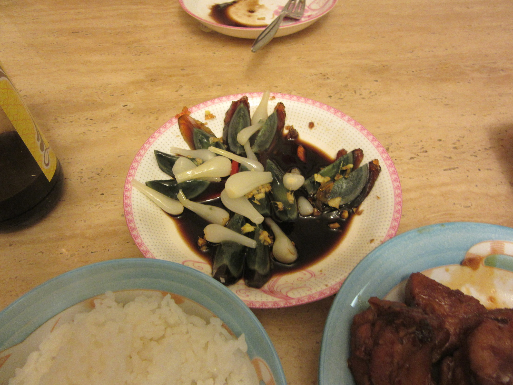
Figure 1: We took some time out to eat these excellent thousand year eggs, along with a lot of other wonderful things!
With the hardware interface done, we then created some Arduino microcode that was very similar to what we had done last weekend: a serial interface controling digital output pins.
// Gameboy
// April 11th, 2015
// By Robert McIntyre, Limdo Chow, and Yuansheng Tana


//// Gameboy Pin Map:
// 1  B
// 2  Select
// 3  Up
// 4  Down
// 5  A
// 6  Start
// 7  Right
// 8  Left

//// Arduino ->  GameBoy Pin Map
// 53  ->  1
// 52  ->  5
// 51  ->  2
// 50  ->  6
// 49  ->  3
// 48  ->  7
// 47  ->  4
// 46  ->  8

static int button_pin_START = 46;
static int button_pin_END = 53;

static int button_A = 52;
static int button_B = 53;
static int button_START = 50;
static int button_SELECT = 51;
static int button_UP = 49;
static int button_DOWN = 47;
static int button_RIGHT = 48;
static int button_LEFT = 46;

void init_button_pins(){
  for(int i=button_pin_START; i<=button_pin_END; i++){
    pinMode(i, OUTPUT);
    // We use low voltage to "press" a gameboy button.
    digitalWrite(i, HIGH);
  }
  // Opens serial port, sets data rate to 9600 bits per second.
  Serial.begin(9600);
}

void press_button(int button_code){
  digitalWrite(button_code, LOW);
  delay(10);
  digitalWrite(button_code, HIGH);
}

int incomingByte = 0;   // for incoming serial data

void serial_press_query(){
  // read from the serial port and directly press the button which
  // corresponds to the byte. Input bits MUST be one of the defined
  // button codes. No error checking is performed.
  if (Serial.available() > 0) {
    incomingByte = Serial.read();

    // DEBUG CODE!
    //Serial.println(incomingByte, DEC);

    press_button((int)incomingByte);
  }
}

void setup() {init_button_pins();}

void loop() {serial_press_query();}
This code is simpler than the LED code because we only support serial communication, and because we are only activating one pin at a time.
Like last time, we also made a simple python program to talk to the Arduino.
serial-send.py
#!/bin/python
import sys
import serial
import os
ser = serial.Serial('/dev/tty.usbserial', 9600)

button_code = int(sys.argv[1])

valid_button_code_START = 46
valid_button_code_END = 53

if (46 <= button_code <= 53):
    ser.write(str(chr(button_code)).encode());
else:
    print("invalid code (need [46,53]):", button_code)
    os.strerror(5)
This time we put the error checking in our python script.
We define a button API with another script:
press-button-cli.pl
#!/bin/perl

$button_codes =
{ "A" => 52,
  "B" => 53,
  "S" => 50,
  "s" => 51,
  "u" => 49,
  "d" => 47,
  "r" => 48,
  "l" => 46};

system("python3", "./serial-send.py", $button_codes->{$ARGV[0]});
With this CLI, we can test that everything works.
Now that everything works, we can build a nice web interface to control the gameboy.
We start with a CGI script that uses our button API to control the gameboy.
press-button.pl
#!/bin/perl

use CGI;
$cgi = new CGI;
$cgi->header();
my $button_name =  $cgi->param('button_name');
if (!$button_name){$button_name = "r";}
`./press-button-cli.pl $button_name`;
print "<html><body>Success!</body></html>";
Next comes the html which will define the structure of our interface.
<!DOCTYPE html>

<html>
  <head>
    <link href='./gameboy.css' rel='stylesheet' type='text/css'/>
    <script src="./lib/jquery-2.1.3.min.js"></script>
    <script src="./lib/jquery.hotkeys-0.7.9.min.js"></script>
    <script src="./gameboy.js"></script>
  </head>
  <body>

    <div class="key-box" id="arrows">
      <div class="button" id="right">
        <img src="images/arrow-right.png" width=80px></img></div>
      <div class="button" id="left">
        <img src="images/arrow-left.png" width=80px></img></div>
      <div class="button" id="up">
        <img src="images/arrow-up.png" width=80px></img></div>
      <div class="button" id="down">
        <img src="images/arrow-down.png" width=80px></img></div>
    </div>

    <div class="key-box" id="other-keys">
      <div class="round-buttons">
        <div class="button" id="a">
          <img src="images/a-button.png" width=100px></img></div>
        <div class="button" id="b">
          <img src="images/b-button.png" width=100px></img></div>
      </div>
      <div class="thin-buttons">
        <div class="button" id="start">START</div>
        <div class="button" id="select">Select</div>
      </div>
    </div>
  </body>
</html>
You can visit this page here.
We need to bind the interface elements to our CGI script using javascript. Even though we're using CGI, we don't actually update the page when we execute our POST commands.
gameboy.js
function key_press(button_name){
    return function (){
        $.post( "./press-button.pl",
                {button_name: button_name});};
}

function click_binding(id, button_name){
    /* Enable an html element to control the gameboy via a keypress */
    $(id).click(key_press(button_name));
}

function keyboard_binding(key_name, button_name){
    $(document).bind('keydown', key_name, key_press(button_name));
}

/* establish controls for the gameboy, both on-screen and keyboard */
function bind_gb_button(div_name, key_name, button_name){
    click_binding(div_name, button_name);
    keyboard_binding(key_name, button_name);
}

$(document).ready(function(){
    bind_gb_button("#right", 'right', "r");
    bind_gb_button("#left", 'left', "l");
    bind_gb_button("#up",'up', "u");
    bind_gb_button("#down",'down', "d");
    bind_gb_button("#start", 'space', "S");
    bind_gb_button("#select",'enter', "s");
    bind_gb_button("#a", 'z', "A");
    bind_gb_button("#b", 'x', "B");
});
This javascript uses functional style to create both a GUI and a keyboard interface.
The last step is to syle everything with css and make the interface look nice. I'm not very good at css, but I think we managed to do a passable job:
gameboy.css
#arrows{
    background: #BBBBBB;
    width: 420px;
    border-radius: 25px;
    margin:10px;
    padding:25px;
}

#right, #left, #up, #down {
    display:inline;
    margin: 10px;
}

.round-buttons{
    padding-left: 100px;
    padding-right: 100px;
    width: 300px;
    margin: 30px;
}

.thin-buttons{
    padding-left: 140px;
    padding-right: 100px;
    width: 300px;
    margin: 30px;
}


#a,#b {
    padding: 5px;
    display: inline;
}

#start,#select {
    border-radius: 25px;
    background: #BBBBBB;
    padding: 10px;
    width: 80px;
    height: 20px;
    display: inline;
}
Tan controlls the gameboy with his phone's touchscreen! We managed to put together a radio controlled gameboy with a touchscreen!
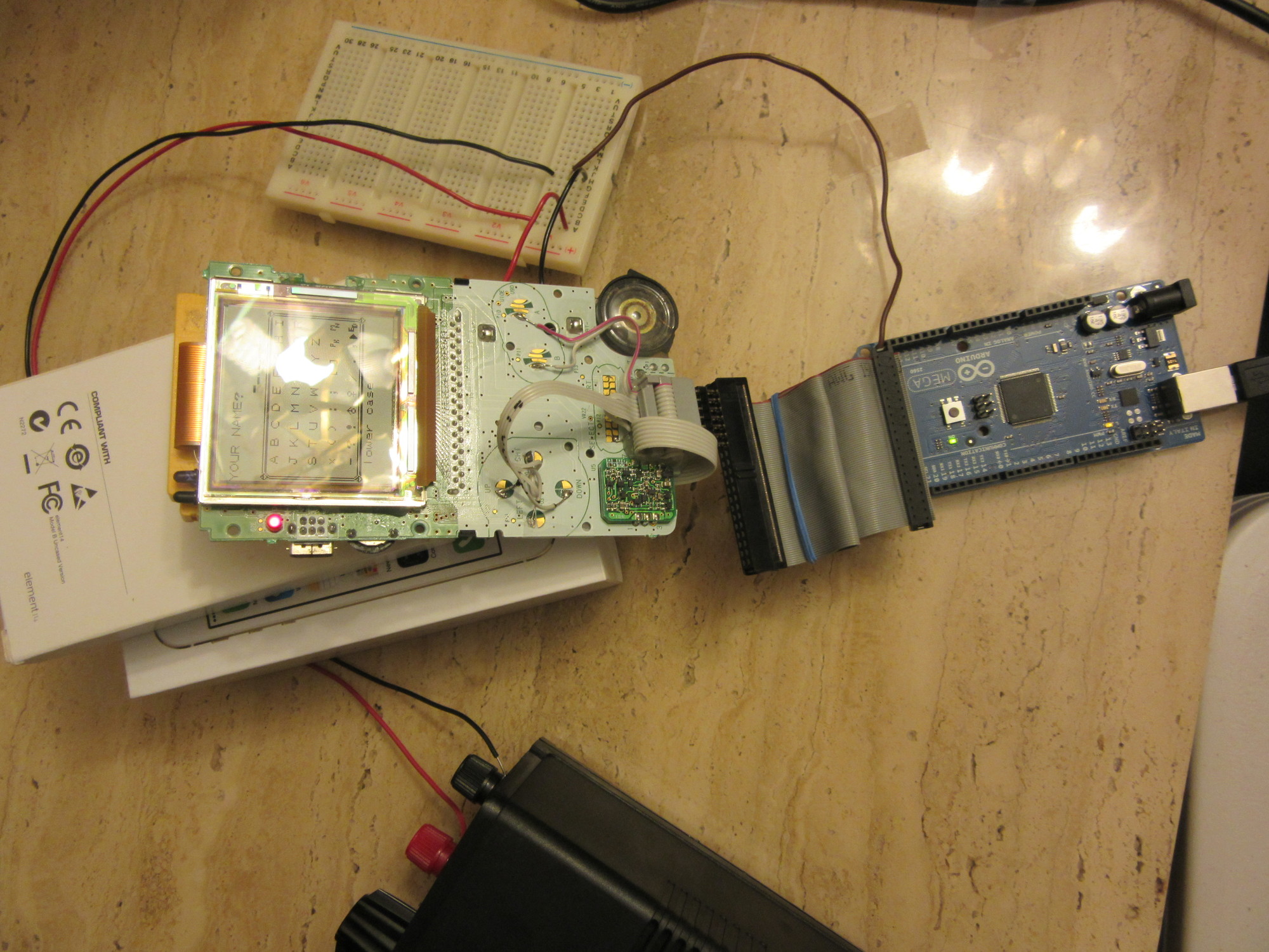
Figure 2: The gameboy fully hooked up to everything.
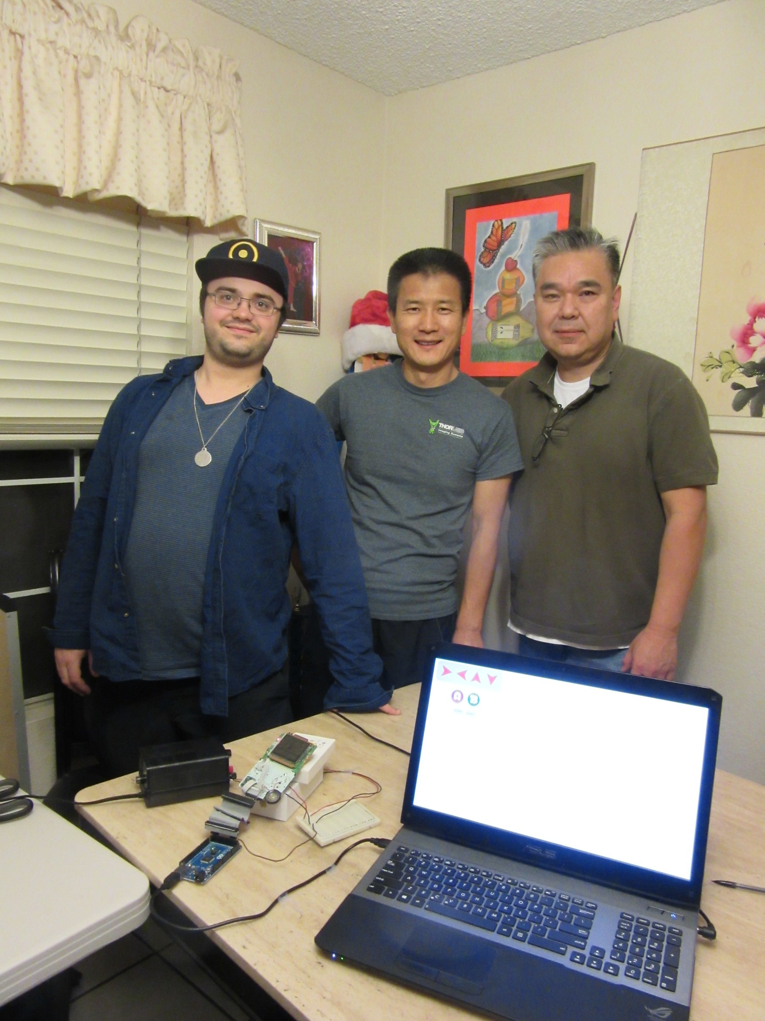
Figure 3: We had a fun time!